



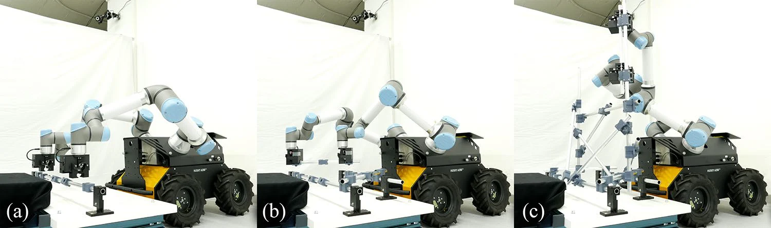
 Physical demonstration
Abstract
This paper presents a robot-friendly scaffolding system that enables autonomous assembly with passive error correction using a dual-function mechanical connector. Conventional tube-and-clamp scaffolding requires precise manual alignment and tightening of flexible joints, which are challenging for automation. The proposed system replaces these manual operations with male and female joints that are pre-positioned accurately along each tube. The joints make use of a tapered-screw feature that performs both alignment and fastening in a single motion, thereby eliminating the need for accurate spatial alignment.
Three experiments validated the approach. An alignment-tolerance test showed reliable engagement of the joints even with ±5 mm translational and ±3° angular deviation. A digital simulation of a multi-story structure confirmed robotic reachability, collision-free insertion, and stability throughout the assembly process. A physical structure with multiple joint arrangements demonstrated the assembly process with a real-world dual-arm robot without any external localization or alignment sensors. Together, the results demonstrate that mechanical self-correction at the joint level can propagate structural accuracy across the entire system.
Results at a glance
Local Correction, System-Level Accuracy
Motivation
Why Scaffolding Needs a Robot-Friendly Redesign
Conventional systems place alignment, error correction, and temporary support in the hands of skilled workers.
Challenges of Tube-and-Clamp Scaffolding
Existing scaffolding systems are designed for humans, making them challenging for robotic automation:
Alignment and Fastening at Every Joint
Tube-and-clamp connectors require a dexterous hand for alignment and fastening.
Image credit: Chenming Jiang and Yi-Hsiu Hung, MAS DFAB Master Thesis 2023, ETH Zurich.
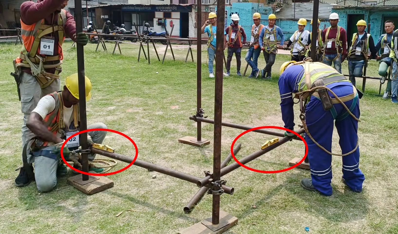
Error Correction and Temporary Support
The assembly process requires periodic measurement and adjustment to correct accumulated errors. When the structure is larger than its builders, temporary support is often needed.
Image credit: source video on YouTube.
Embedded Geometric Intelligence
Instead of asking robots to reproduce skilled manual correction, alignment can be designed into the joint itself.
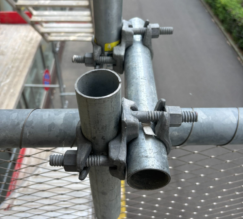
Legacy Joints for Scaffolding
General-purpose clamps depend on human dexterity to position, align, and fasten each connection.
Photo credit: project team.
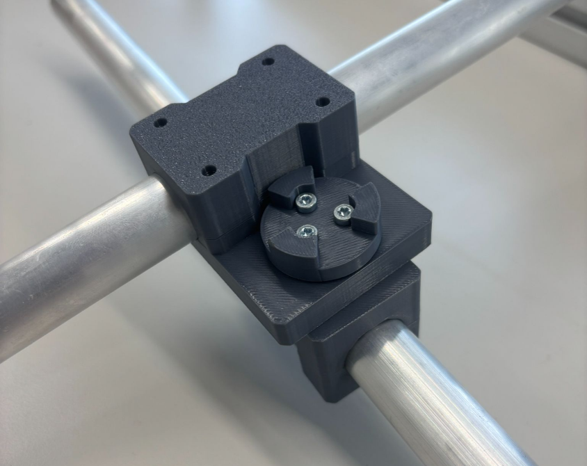
This Work: Custom-Designed Joints for Robot Tools
Pre-positioned geometry provides passive alignment and a predictable interface for robotic assembly.
Photo credit: project team.
Interactive Demo of Planned Keyframes
Interactive Demo
Rotate and zoom the multi-robot workcell, then scrub through the exact discrete IK states used to validate the assembly and temporary-support sequence.
On phone browsers, loading the interactive assets may take 1–2 minutes. Please be patient while the model downloads and initializes.
Selected dataset
Loading sequence catalog…
Preparing dataset information
Interactive WebGL model
Loading 3D geometry
Drag to rotate · wheel or pinch to zoom · right-drag to pan
1 / 1
Sequence frame
Loading sequence catalog.
Each slider position is a solved design keyframe, not an interpolated animation frame. Installed bars remain visible as the structure grows; active bars and support-release events are highlighted.
Experimental validation
From Connector Tolerance to Autonomous Assembly
Three studies test the system at joint, structure, and robotic workflow scales.
Physical demonstration
Dual-Arm Assembly Without External Alignment Sensors
A mobile dual-arm robot follows the planned trajectory to install horizontal, vertical, diagonal, and extension tubes. Pre-positioned joints and passive self-alignment keep the completed structure within ±2.5 mm global deviation.
- Representative ground, horizontal, and vertical connections
- One end-effector combines tube gripping and screw tightening
- Mechanical correction reduces the sensing burden on the robot
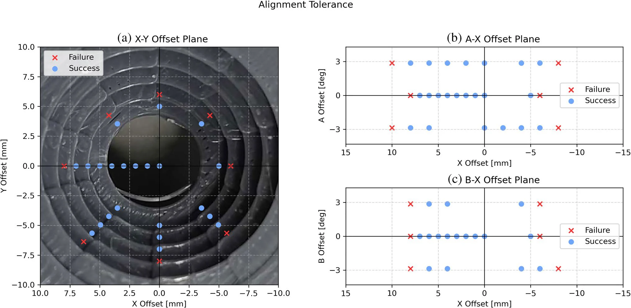
Alignment tolerance
The Connector Corrects Error as It Tightens
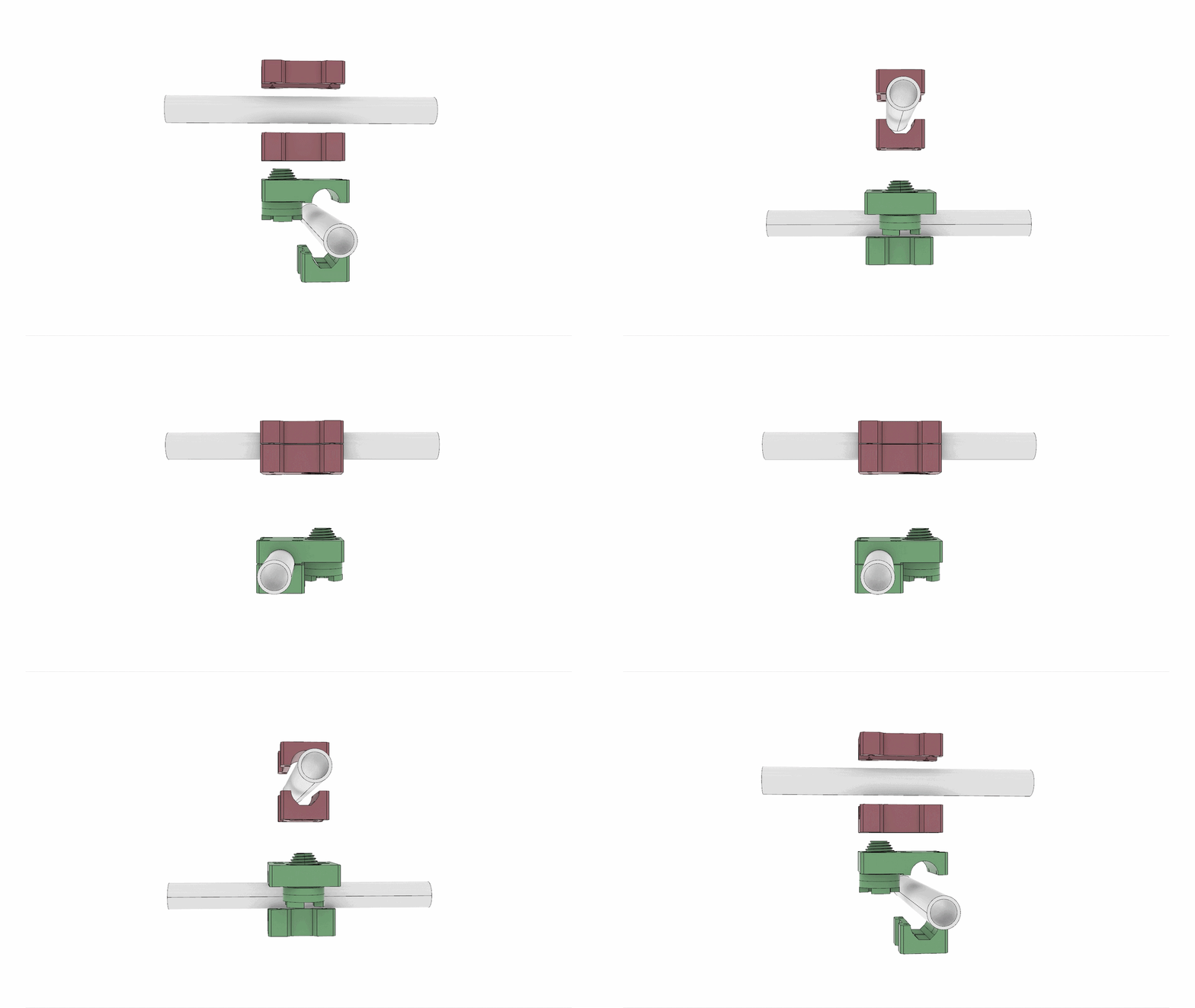
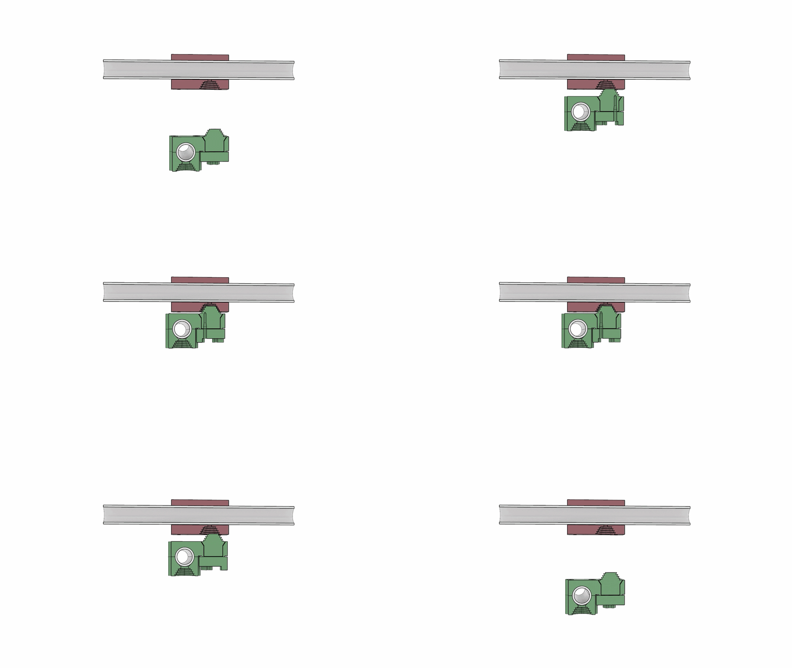
Two robot arms introduce controlled translational and angular offsets before insertion. The tapered interface consistently guides the joint halves into engagement within the validated tolerance envelope.
Multi-story simulation
Reachable, Stable Assembly at Architectural Scale
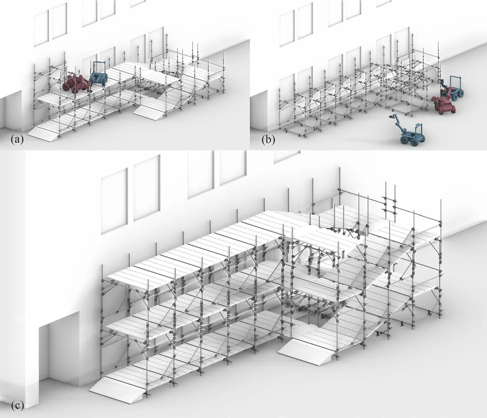
A digital study validates a 376-tube, 802-joint scaffolding structure. Each step is checked for robot reachability, collision-free insertion, mobile-base access, and temporary structural stability.
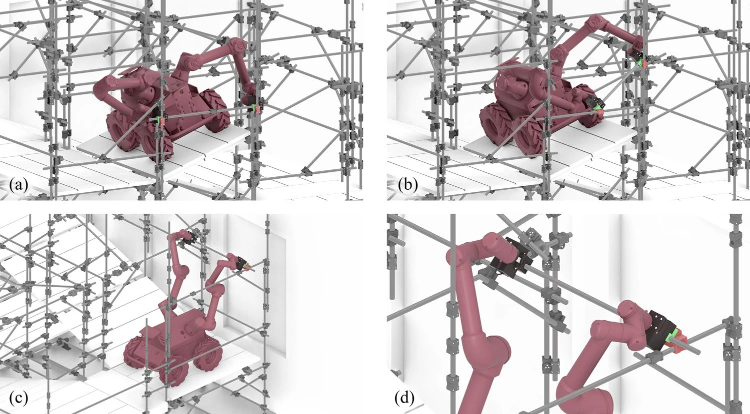 Reachability and collision verification
System design
Robot-Friendly Design
Rethinking robotic assembly as a holistic system that includes the connector, the structural system, and the assembly process.
01
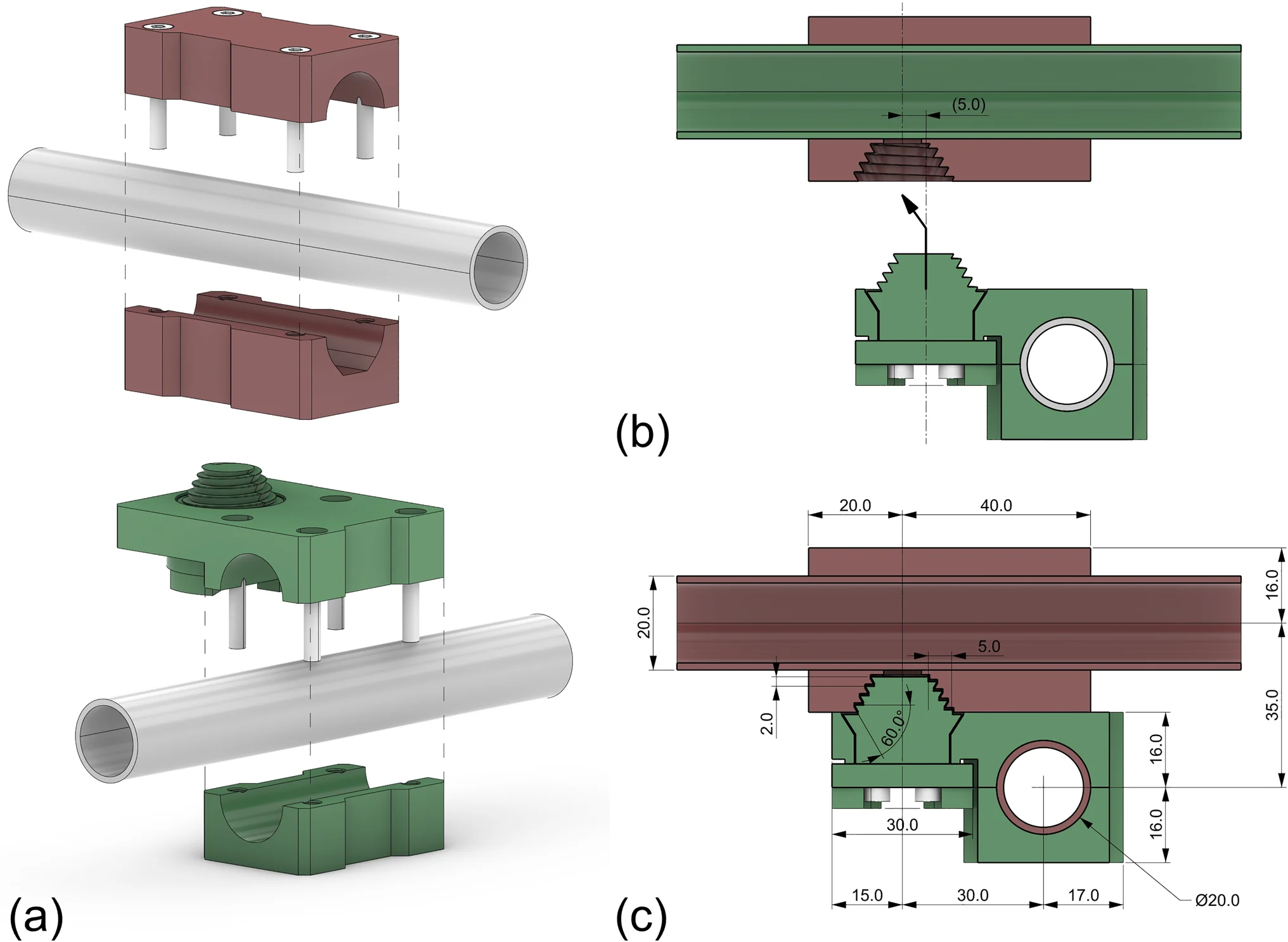
T20-5 Connector
Complementary tapers convert screw rotation into axial tightening and radial centering, combining alignment and fastening.
02
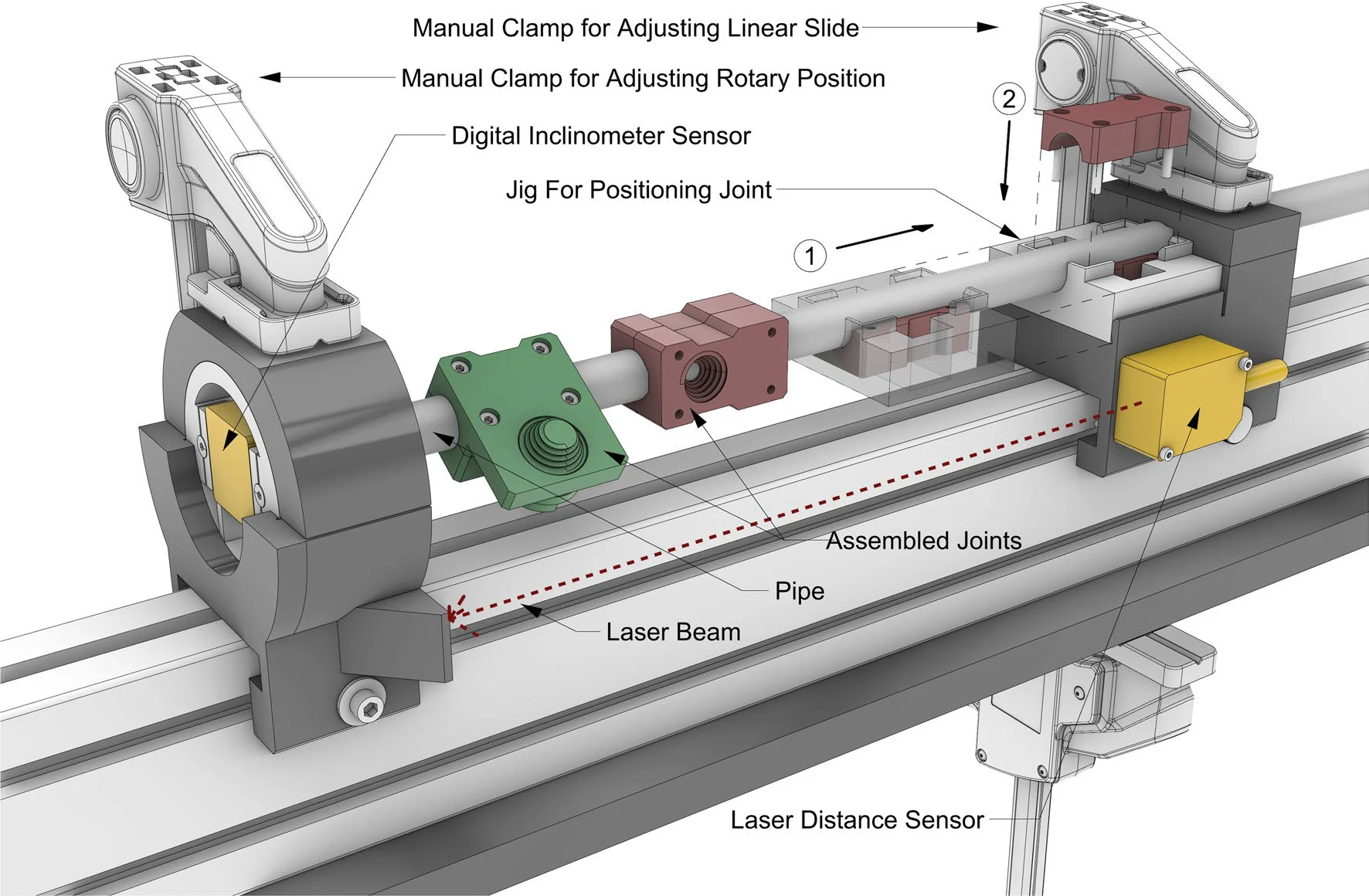
Pre-Positioned Joints
A sliding jig accurately indexes connector positions and rotations on individual tubes before robotic assembly begins.
03
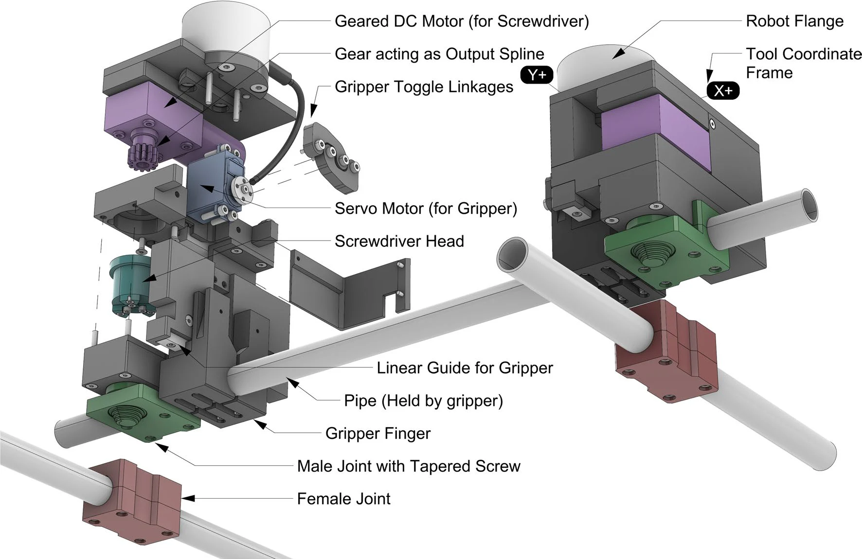
GT1 End-Effector
A lightweight tool grips the tube and drives the connector, allowing two arms to position and tighten both joints synchronously.
Work-in-Progress
Joints and Tools
The system's second iteration improves robotic reachability with a more compact tool. The same tapered screw thread is added to the back of each joint, allowing the end-effector to hold it without requiring free space around the bar.
This enables denser joint placement and extends two-way joints into stackable multi-way joints for more complex structures.
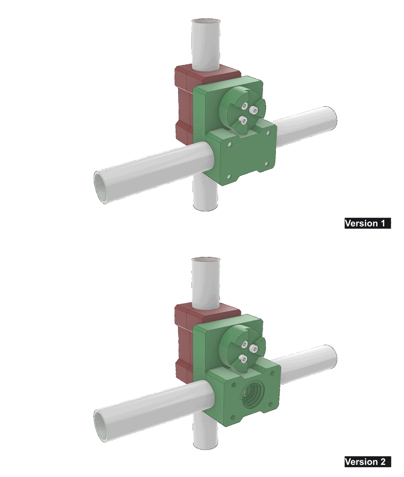
Joint Iteration
Rear-side tapered threads make the joint accessible without requiring free space around the bar.
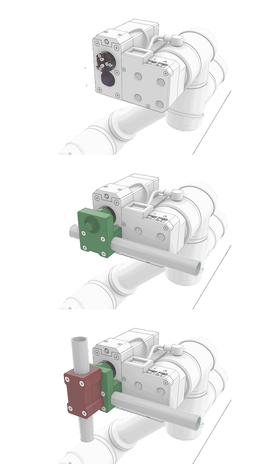
Compact Tool–Joint Interface
The revised interface lets the end-effector grasp the joint from behind and install denser, multi-way assemblies.
03
Semi-Automated Fixture
Robot Planning and Control
01
Dual-Arm Constrained Planning for Bar Transfer
02
Dual-Arm Compliant Controller
Reference
Citation
@article{leung2026robotfriendly,
  title   = {A robot-friendly scaffolding system with passive error correction using tapered screw connectors},
  author  = {Leung, Pok Yin Victor and Huang, Yijiang and Liu, Yen-Ting and Genhart, Jakob and Li, Zihao and Garrett, Caelan and Coros, Stelian},
  journal = {Construction Robotics},
  volume  = {10},
  pages   = {29},
  year    = {2026},
  doi     = {10.1007/s41693-026-00191-3}
}Contribution Statement
Victor Leung*
Conceptualized the tapered screw and multi-story vision; designed and built the robotic end effectors, including their electronics, control software, and mechanics; designed and built jig v2 for joint installation; implemented and supervised the detailed scaffolding-system design; contributed ideas to the robot calibration procedures; and wrote the paper.
Yijiang Huang*
Led the project and managed the team; acquired funding; developed the robot monitoring, planning, and control infrastructure; developed the LM planning pipeline for the Antenna and kissing experiments; developed the Grasshopper-based keyframing script; led the robot calibration procedures; and led the Antenna experiment.
Yen-Ting (Bob) Liu
Designed and built jig v1 for joint installation; contributed to the detailed scaffolding-system design; used the keyframing script for multiple design case studies, including the multi-story experiment; assisted with the Antenna experiment and hardware acquisition; and produced image and video renderings.
Jakob Genhart
Developed the ROS 2 control infrastructure for all Husky robots; led the compliant-controller investigation; and led the kissing experiment.
Zihao Li
Developed a work-in-progress constrained dual-arm planner for bar transfer; conducted early investigations into TAMP formulation and experiments, including optimization for computing multi-robot keyframes and assembly and support sequence search.
Caelan Garrett
Contributed ideas for planning formulations and algorithms.
Stelian Coros
Provided general supervision; acquired hardware funding; and contributed ideas for project contextualization and technical approaches.
* Equal contribution
Acknowledgement
The following colleagues were not part of the team at the time of submission, but have contributed to this project as it continues to evolve:
Huang Su
Contributed to the latest physical demonstration involving the new joint design, jig system, robot tool, and robot workflow; contributed to the renovation of the lab's robot infrastructure; operated the jig to build the demonstration used in the FoC workshop and teaser video; operated and maintained the motion-capture system; contributed to the new Rhino-based keyframe software; and produced documentation, images, and video renderings.
Jung In Seo
Contributed to jig operation and documentation from the FoC workshop onward, as well as motion-capture coverage analysis and optimization.
Keith Lee
Contributed to the early-stage structural analysis and tube sizing for the multi-storey scaffolding that enables robots to climb on it.
This project is partially supported by CityUHK Grant (9610746) and by the SNSF Ambizione Grant (Grant No. 223384).